What is the CAN Bus?
Cars have drastically evolved since their creation. Instead of being internal combustion engines with four wheels and a seat, cars like the Tesla boast large computers on their dashboards and doors with no handles. Even more, cars can drive themselves.
Drivers continue to reap the benefits of technological advancement and never even notice all the inner workings that make it possible. Cars contain vast amounts of features, triggers, buttons, sensors, and more to bring one cohesive driving experience. We never even stop to think how when we change our gear to “reverse” the dashboard screen shows the backup camera footage. Or how when we finish a turn the blinker automatically stops blinking. One might say, “well there is a connection from the gear to the screen, telling it to read in the backup camera when the gear is on the reverse position”. While that could work, think about all the connections that would be needed for every feature the car brings. Connecting each feature would create a labyrinth of connections that would be impossible to wire. So how do we have million feature cars? The answer is the CAN Bus.
CAN Bus Overview
The Controller Area Network (CAN) Bus is like the nervous system of the car. The devices in the vehicle, or Electronic Control units (ECUs), are like the parts of the body that both transmit and receive information through the CAN Bus. Some ECUs include airbags, audio systems, and power steering. In cars today, there are 80 or more ECUs. The CAN Bus allows each of them to communicate without needing to all be connected to one another. The CAN Bus offers a centralized path for ECUs to transmit messages to one another.
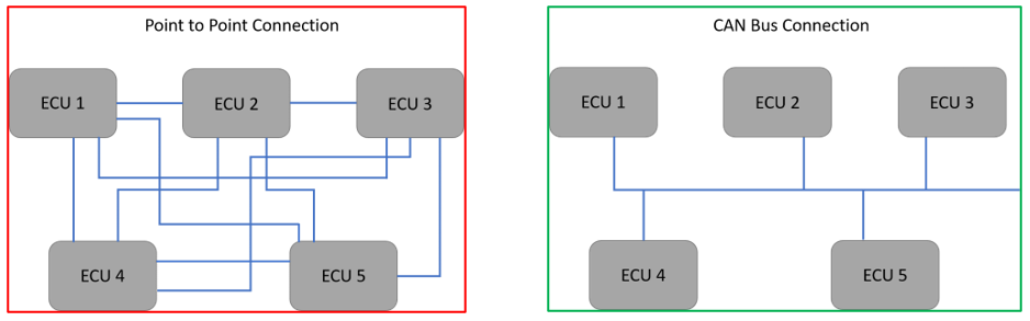
As seen in the diagrams above, with the CAN Bus, the wiring is much simpler and because of that, more low cost and efficient. Every ECU can communicate with each other through a centralized system.
CAN Bus Nuts & Bolts
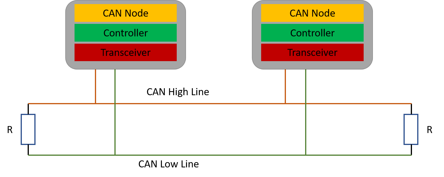
In the CAN Bus network, there exits two lines that complete the network, CAN High and CAN Low. These are bookended by resistors (acting as terminals) to prevent data from being reflected from the lines and echoed back in (which would cause interference). Each ECU has three parts that play roles in the CAN Bus: CAN Controller, CAN Transceiver, and CAN Node (the microcomputer inside the ECU). In a functioning CAN Bus, the three interact based on whether they receive or send a message in the network.

ECU Sends a message:
-
CAN Node (microcomputer) sends transfer data to the CAN Controller
-
CAN Controller sends data to CAN Transceiver
-
CAN Transceiver processes data and converts it to electrical signals that then get sent out into CAN Bus data lines
ECU Receives a message:
-
CAN Transceiver receives message from CAN Bus data lines
-
CAN Transceiver converts data and sends it to CAN Controller
-
CAN Controller receives data from Transceiver, processes it and relays the data to the CAN Node
-
CAN Node checks to see if data received is important for their functions or not
-
If data is important, data is accepted and processed
-
If data is not important, data is ignored
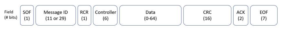
Each CAN Bus message in the network is called a CAN frame. These frames can either be broadcast to all ECUs in the CAN Bus, or they can be directed to specific ECU. The standard CAN frame has the same 8 field format.
Standard CAN Frame Structure
-
SOF: Start of Frame. Signals the beginning of a frame with a dominant ‘0’ bit (versus the recessive ‘1’ state).
-
Message ID: Defines the priority of the message based on which CAN Node is delivering the frame. The lower the number, the higher the priority. Standard arbitration ID’s are 11 bits and Extended arbitration ID’s are 29 bits. The ID is based on the Node, and not the actual message being delivered. Lower priority CAN Nodes must wait for openings to transmit their messages.
-
RTR: Remote Transmission Request. Part of the arbitration portion of a message frame. Indicates whether the message frame is a data frame or a remote frame (“0” for data frame and “1” for remote request frame).
-
Control: Consists of six bits. It includes the data length code (4 bits) and two bits reserved for future expansion. Shows how items of data are being sent in the frame. Allows receiving nodes to verify that they have received all the information sent.
-
Data: Contains the data being transferred. Can be anywhere from 0-64 bits.
-
CRC: Cyclic Redundancy Check. This field is to make sure there are no transfer faults, also called Safety Field.
-
ACK: Acknowledge Field (or Confirmation Field). Sends a signal to transmitting node that the message was received. Likewise, if an error is detected, the transmitter is notified of the error and resends the data.
-
EOF: End of Frame. Marks the end of the CAN frame.
CAN Bus Implementation in a Vehicle
As mentioned earlier, modern vehicles have up to 80 or more ECUs. While the CAN Bus offers a much more efficient method of ECU communication than point to point, handling 80+ ECUs through one CAN Bus channel could lead to information backup. To mitigate this problem, there are several CAN Bus systems that feature in a vehicle, and they are grouped by priority and function. These groups include Powertrain, Body, Comfort, Chassis, and more. These subnetworks can be connected by a gateway that allows for communication between CAN Buses if necessary. This gateway is normally the Body computer but can also be the Instrument Cluster or a different computer.
Each subnetwork operates on a different speed (low, medium, and high) based on the priority of their data/functions. For example, the CAN Bus controlling Engine data would operate on a high-speed network since its data is very high priority and critical for the car to properly function. A low-speed CAN Bus would feature ECUs such as interior lighting, in-cab entertainment, etc. High speed CAN Bus networks are the most expensive, so creating lower speed buses with less critical devices helps cut costs while maintaining efficiency.
CAN Bus Compatibility with External Devices
The centralized CAN Bus system allows for easy implementation of external telematics devices such as Positioning Universal’s FT7500. The FT7500 syncs to the vehicle through simple, seamless installation and then can read data from all the ECUs present in the vehicle. From there, the FT7500 reads the Vehicle Identification Number (VIN) and sends it to the cloud. where it is parsed. Then a file is returned that allows the FT7500 to read custom parameters from that specific vehicle. This allows for exceptional customization of monitoring from vehicle to vehicle, optimizing fleet management.
Conclusion
The CAN Bus allows for a centralized, efficient method for car devices to communicate from one to the other. By creating this centralized system, external devices like the FT7500 and its paired AI Fleet Camera Solution can seamlessly connect and access critical data from all the ECUs in the vehicle, tremendously improving fleet management and fleet safety.
Related posts
The Advantages of a Dual-Facing Dashboard Truck Camera
In the fleet management sector, dash cameras have proven to be more beneficial t
Cellular Frequency Bands and their Impact on Telematics
On episode 2 of Well’s Words, Positioning Universal CEO Mark Wells briefly dis
Positioning Universal and Syntiant Unveil AI-Powered Sound Sensing Telematics Device
New Edge AI Solution Brings ‘Smart Hearing’ to Vehicles, Detecting Crashes,
Leave a Reply